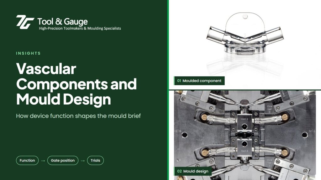
In vascular intervention devices, small interfaces deserve detailed attention. A hub must connect as intended, a housing must locate its internal parts, and a locking feature must engage reliably. For the team developing an injection-moulded component, these functional relationships should shape the mould brief from the beginning.
Introducer systems illustrate the point: commercial designs can incorporate a sheath hub, valve and locking dilator interface. Their arrangement varies by device, but the engineering question is consistent: how will the manufactured components work together?
How does device function shape the mould for a vascular component?
The surfaces that locate, retain, seal or guide another component should set the priorities for the mould. For a proposed moulded hub, connector or valve housing, identify those surfaces and separate them from surfaces where wider variation may be acceptable.
Consider a housing that locates a separate seal. The tooling discussion should cover the seal pocket, assembly datums and any parting line near the interface. The drawing and acceptance criteria should make clear what needs dimensional verification and what requires an assembly or functional test.
The moulded housing is only one contributor to performance; the seal, mating parts and assembly process also matter. Polymer selection therefore needs to reflect the intended assembly and use, with suitability assessed by the customer’s design team.
Where should the gate go on a moulded vascular component?
The gate should sit away from assembly and sealing interfaces where possible, because a position that simplifies filling may leave a vestige where it causes problems. Flow around holes can create weld lines, so their location deserves attention where a feature will be loaded.
Use the DFM review to examine these trade-offs alongside wall thickness, draft and ejection. Mould-flow analysis can help investigate filling behaviour, but it does not replace trials and testing of the actual component.
Tool & Gauge, based in Ireland, supports component DFM and materials selection, with a focus on polymer problem-solving for complex small parts. For a proposed vascular component, bring material requirements into the tooling discussion alongside geometry. Our mould-flow analysis and mould design services help develop the manufacturing approach.
How should a mould handle design changes from R&D to launch?
During R&D, interface dimensions may change as the device assembly evolves, so identify likely development areas early and discuss whether replaceable inserts or other tooling provisions would be appropriate. Avoid treating every early drawing as a settled production specification.
When moving towards commercial manufacture, review the effect of the final material, cavity strategy and process on the agreed acceptance criteria. A successful prototype establishes useful evidence; the production configuration still needs its own assessment.
Why bring mating parts into a mould review?
Mating parts show how the component must perform in the assembly, which a drawing alone cannot. For R&D and manufacturing engineers, the most useful supplier discussion combines component geometry with assembly intent. For sourcing teams, it clarifies what the mould quotation includes and which development decisions remain open.
Frequently asked questions
Weld lines form where flow fronts meet, often around holes, and can weaken a feature that carries load. Reviewing flow and gate position during DFM helps keep weld lines away from critical features.
No. Mould flow analysis helps predict filling behaviour, but it does not replace trials and testing of the actual component. Tool & Gauge uses mould flow analysis alongside mould design, trials and metrology.
Replaceable inserts or similar tooling provisions can let interface dimensions change as the device develops, without rebuilding the whole tool. Tool & Gauge can discuss these options during the DFM review.
Developing a vascular component? Share your drawing, material questions and critical interfaces with our team in Ireland at info@tag.ie, and we’ll review the DFM and mould approach with you.